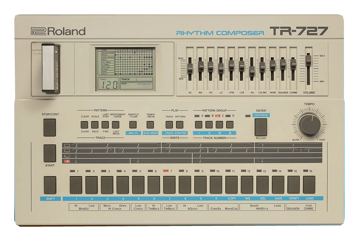
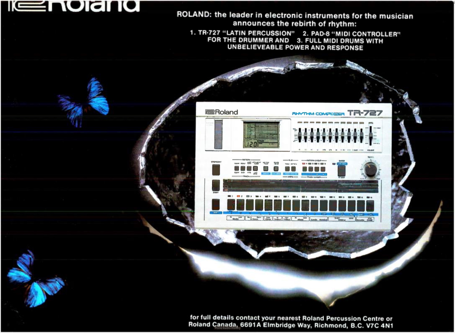
1. Pattern memory is not sound memory. Program ROM tells the CPU how to operate; two battery-backed CMOS SRAMs retain the player's patterns and tracks. The two sound ROMs sit on the voicing board and retain fixed PCM waveforms without the battery. Losing the backup cell can erase an arrangement, but it cannot erase a conga sample.
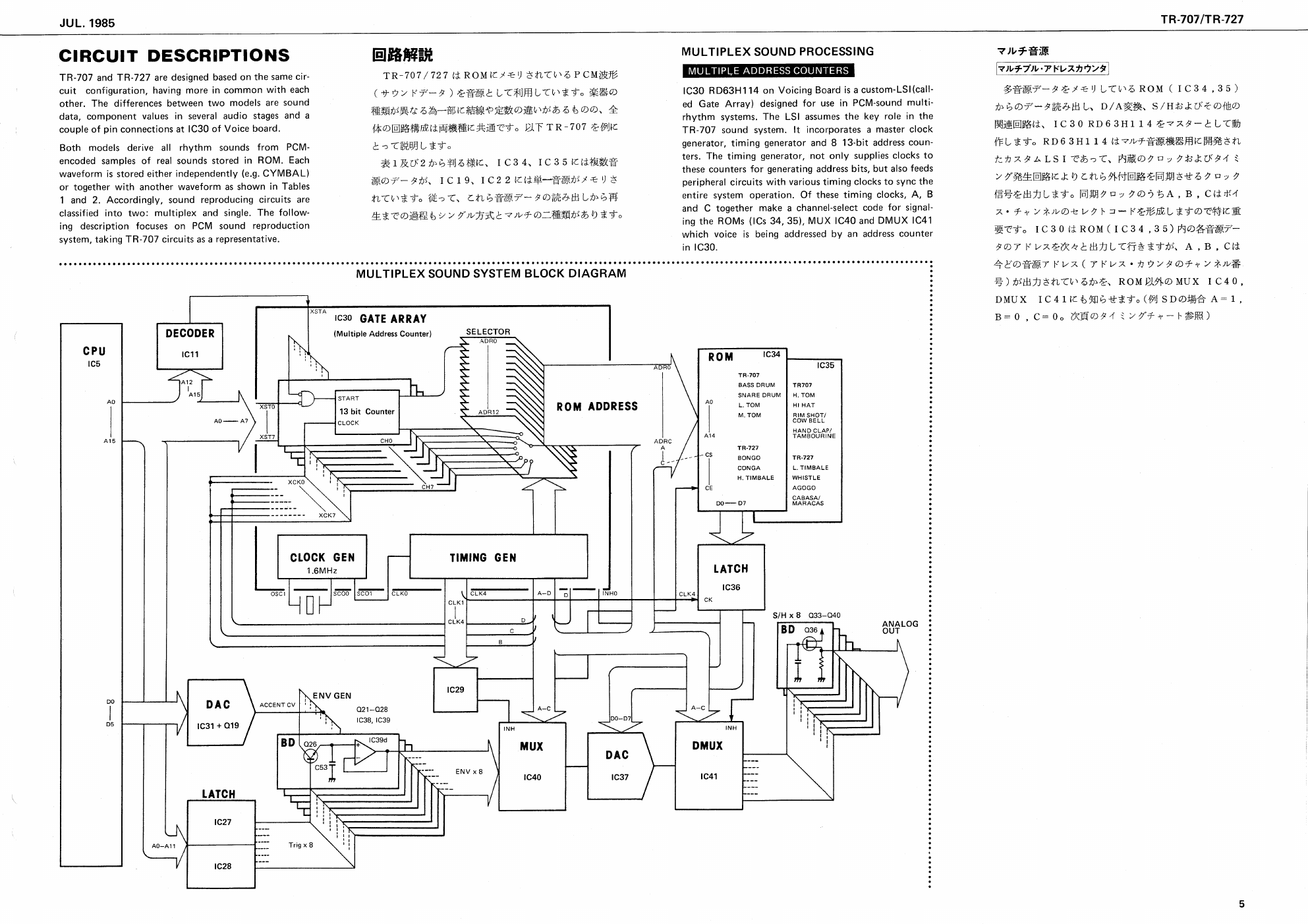
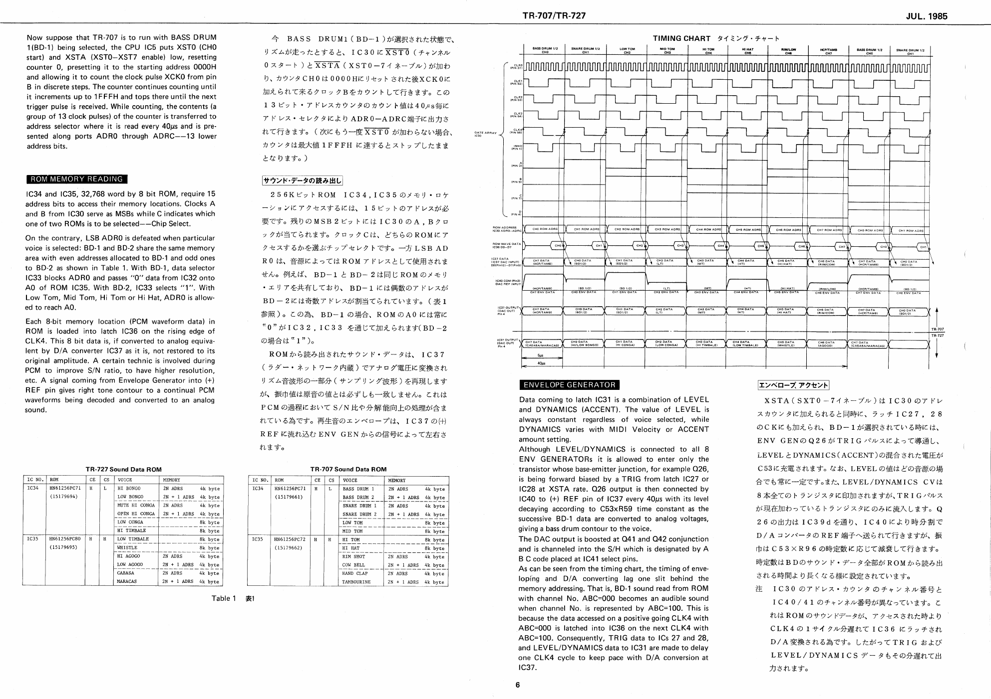
2. The RD63H114 runs eight shared readers. IC30 contains the master clock, timing generator and eight 13-bit address counters. When a voice is triggered, one counter restarts at 0000H and advances every 40 microseconds. Address and channel-select signals tell the two sound ROMs, the data latch and the later multiplexer which percussion waveform is active.
3. The shared ROM map is economical. High and low bongo share one 8 KB region as alternating addresses; IC32 and IC33 set the lowest address bit to choose the articulation. Mute/open-high conga share another region, while low conga, high timbale, low timbale and whistles receive 8 KB allocations. High/low agogo and cabasa/maracas use paired 4 KB allocations.
4. Digital words become ten analogue lanes. Latch IC36 captures each eight-bit PCM word; the resistor ladder around IC37 converts it to a stepped voltage. IC40 and IC41 then time-division-multiplex and demultiplex that stream into eight sample-and-hold/envelope lanes. The dedicated voices add two more, producing ten-channel polyphony.
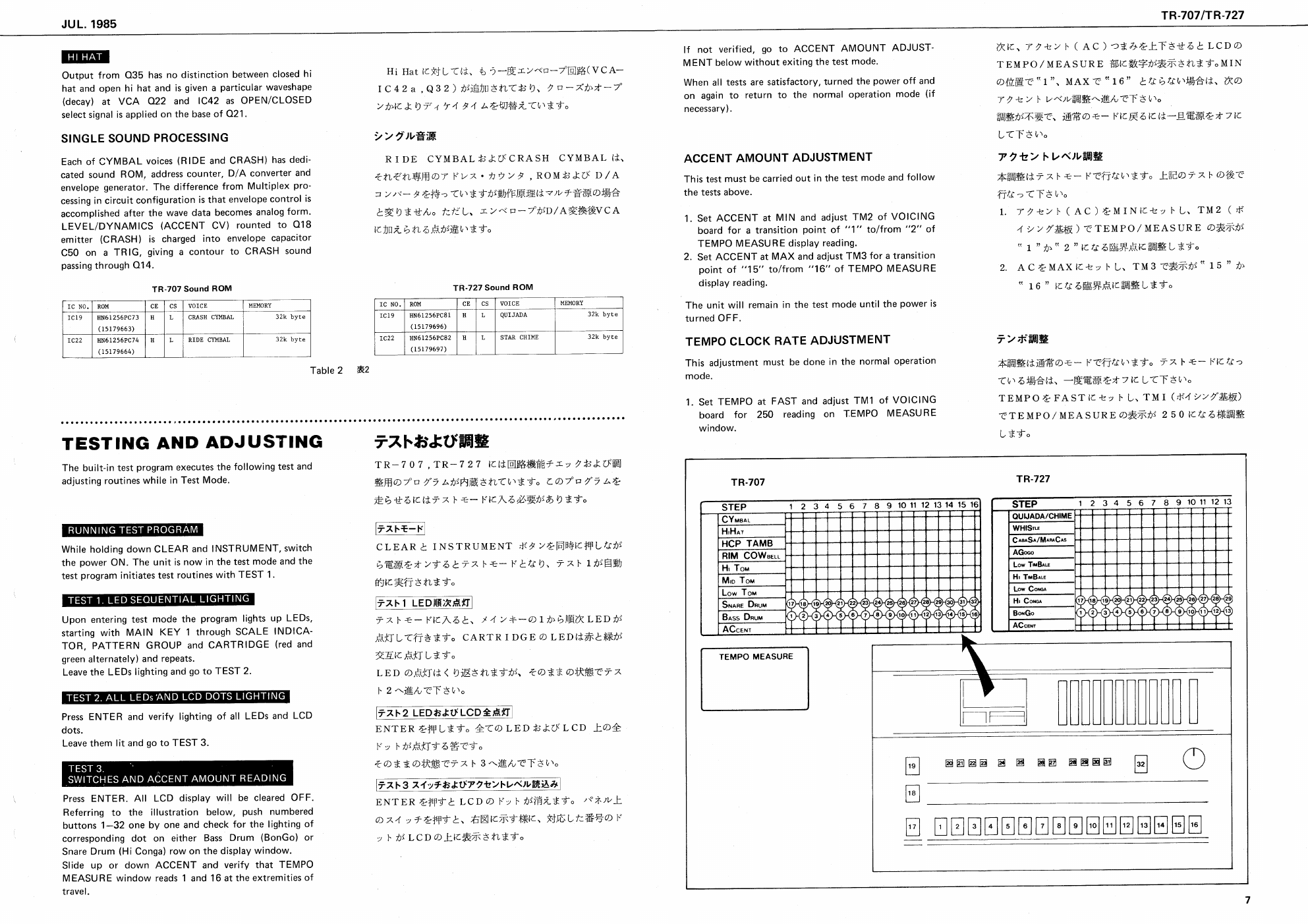
5. Quijada and Star Chime are dedicated. IC19 holds the 32 KB Quijada waveform and IC22 holds the 32 KB Star Chime waveform. Each has its own address counter, D/A converter and envelope circuit rather than entering the eight-channel shared converter. The documentation establishes this separate route; it does not state why Roland selected those two sounds for it.
6. Accent is reconstructed after the ROM. IC31 converts six-bit control data into a voltage combining fixed Level and variable Dynamics. Dynamics follows MIDI velocity or the panel's Total Accent amount. Trigger latches select one envelope transistor at a time; the channel's resistor-capacitor time constant controls how its level falls after conversion.
7. The analogue board finishes the identity. Sample-and-hold, envelope, VCA, filter, fader and output components differ where the percussion voices require different bandwidth and decay. This is why replacing the 707 ROM data alone would not completely turn a 707 into a 727: the factory parts list identifies different voicing and volume boards as well as different samples.
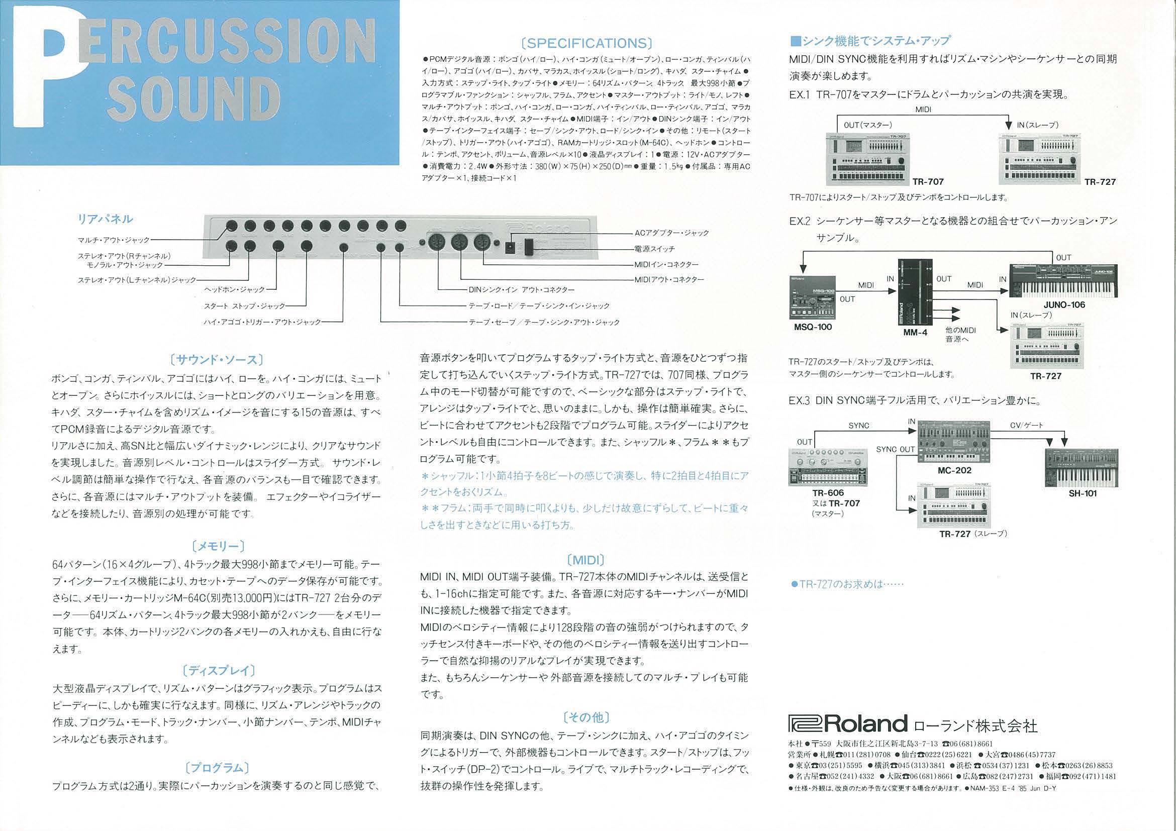
8. The output jack is part of the mix. Each individual output uses a switching contact to remove its group from the master bus. Before blaming the sound ROM for a voice missing at the main output, compare the individual output and inspect that contact. The machine's routing is an active part of diagnosis.